Software interface
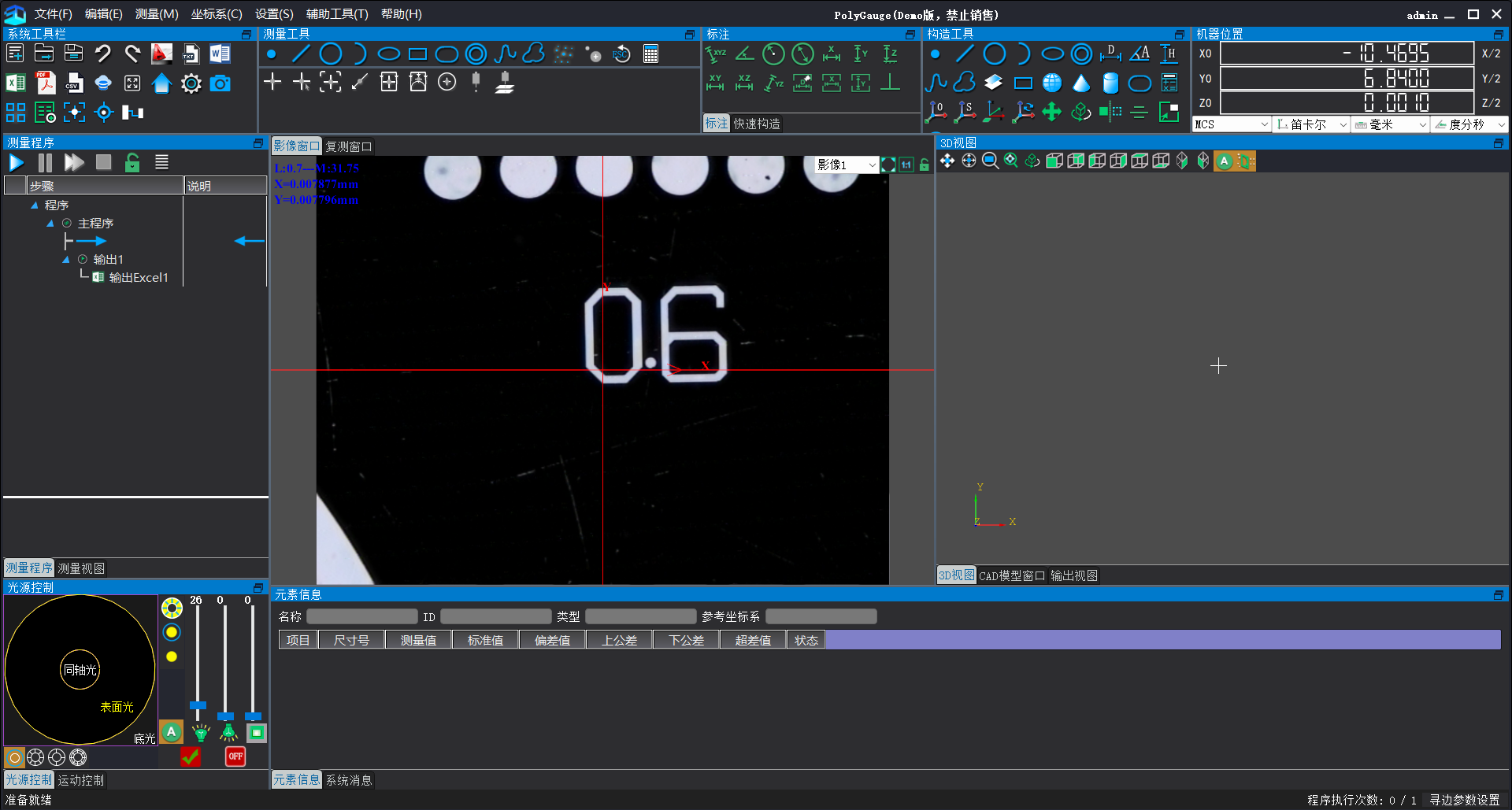
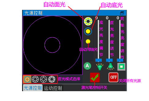
Light Source Control
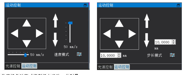
Motor control
Group Measurement & Create Template Measurement
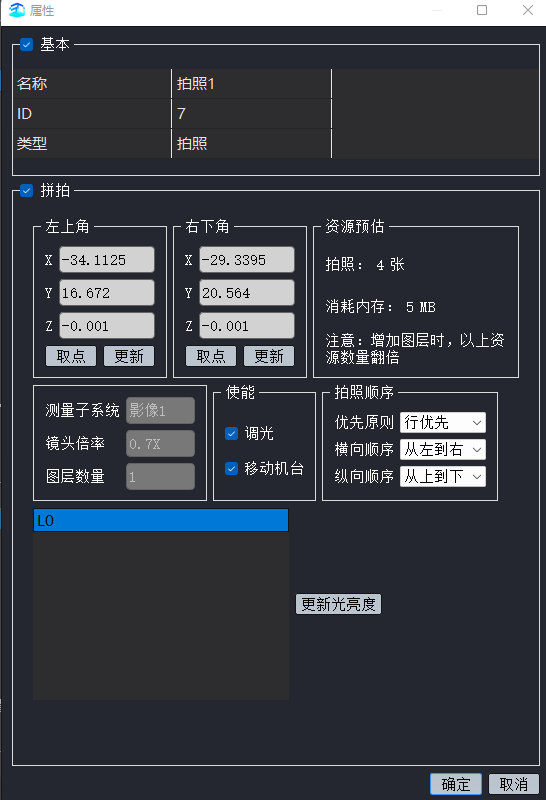
Click the "Pin-Paste  Measurement" button to open the measurement settings interface as shown below:
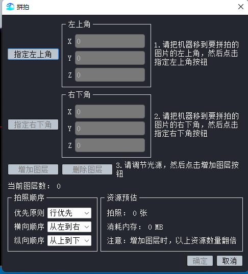
Move the machine to the upper-left corner of the workpiece requiring assembly measurement, click the designated button there, and set the starting position for assembly.
Then move the machine to the lower-right corner of the workpiece, click the designated button there, and set the workpiece's end position.
After adjusting the light source brightness, click the Add Layer button, set the photo capture sequence, then click OK. The software will begin composing the images.
Photo capture sequence: The primary task is to plan the shooting path for composite imaging. For example, with a 40-inch rectangular display panel, capture only the edges of the product; the central area without measurement dimensions does not require composite imaging. The software must capture images in four regions, so the path must be carefully planned to avoid unnecessary routes and improve efficiency.
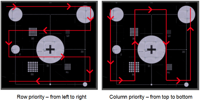
Priority Principle: Set whether the stroke path runs horizontally (row priority) or vertically (column priority).
Horizontal order: When assembling horizontally, should you start from left to right or from right to left?
Vertical order: When assembling vertically, should you start from top to bottom or from bottom to top?
After completing the stitching measurement, the standard procedure involves setting up coordinates and programming to finish the measurement. Here, we introduce an alternative method—creating a template. The image below shows the result of stitching measurement:
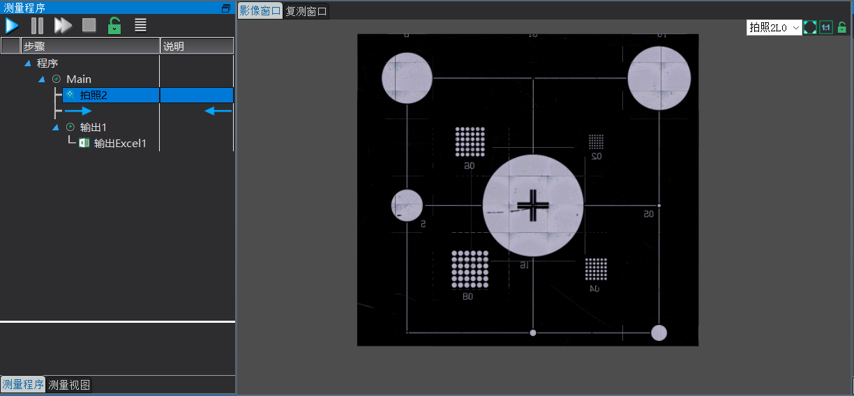
Then immediately create a template measurement:
Click Create Template  Measurement to open the following window:
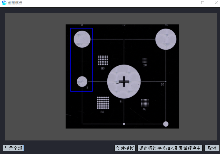
Chose upper-left corner circles (Note: When creating a template, select the product's unique features), click Create Template, and add it to the measurement program. Then capture edges to establish coordinates, extract all elements, calculate distances, manage tolerances, and output data. Finally, save the program to complete programming.
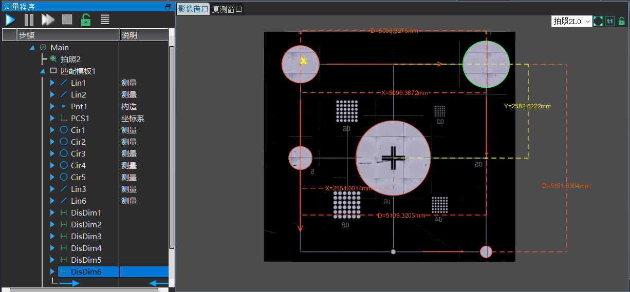
Since a template has been created here, the product is slightly misaligned. After re-assembling it, simply ensure that all features of the template are captured in the image, and the software will complete the measurement.
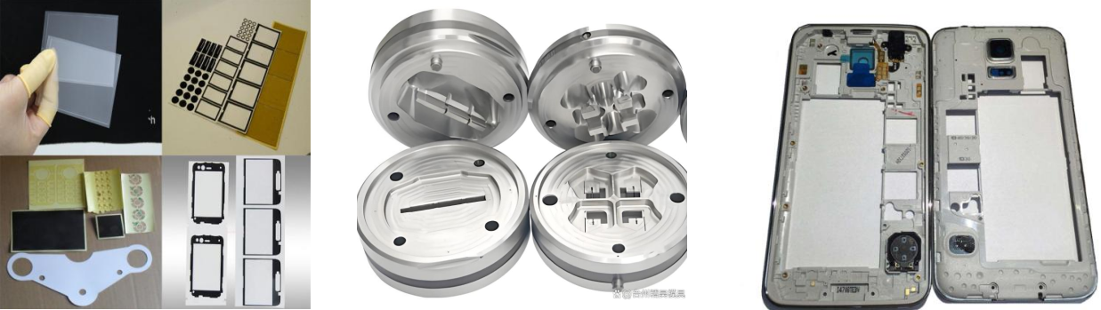
With a wide-field lens, measurement efficiency is significantly improved for products in certain industries (such as die-cutting or circuit board manufacturing). Essentially, after capturing the images, all dimensional measurements can be completed. For example, using an 80×60 mm wide-field lens to measure a 400×300 mm product theoretically requires only 25 photographs to cover the entire product. At a measurement rate of one image per second, the entire measurement process takes approximately 25–28 seconds. Compared to traditional methods, this approach achieves at least a fivefold increase in measurement efficiency.
Key points for image stitching measurement: Avoid over-sizing the frame capture, as the resulting image may contain hundreds of millions of pixels. Enlarging the frame expands the edge detection search area, prolonging the software's boundary search time. Consequently, the measurement process—from image capture to data output—may consume significant time, compromising measurement efficiency.
Before stitching, configure the  displacement tolerance between images in the system settings—specifically, the number of millimeters by which the rear of the first photo overlaps with the front of the second photo (the tolerance should equal the machine's positioning accuracy error plus the pixel calibration value; adjustments can be made based on actual measurements, as excessive overlap may cause image discontinuities), as shown below:
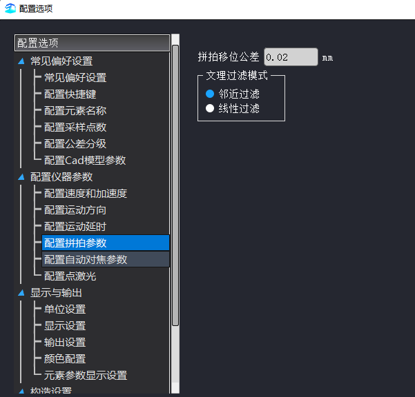
Neighboring filtering: When images displayed in screen are enlarged, pixel grids appear; when zoomed in, the images exhibit jagged edges.
Linear filtering: When the displayed image is enlarged, no pixel grids appear; when zoomed in, the edges appear smoother.
After editing the program, you can also modify the stitching positions. Right-click the shooting command point in the element list and select Properties to open the dialog box (as shown below), where you can update the stitching coordinates, light source brightness, and shooting sequence.